Yes, I bought a new radio. Yet another one. Why, when I already own so many? Because this one was inexpensive, highly-reviewed, and compact, so it would encourage me to toss it in my pack on trips for which I would not want to spend the effort (or allocate the space in my bags) to a larger, more-capable radio.
First impressions follow:
It’s Small
Like, really small. Maybe the size of two decks of playing cards (but a little thicker). And surprisingly light. On the latter point, probably not too durable. But it is easy and painless to take with me. Just took it to the neighbourhood park, and it’s amazing how low the noise floor is once you get even a short distance away from houses and power lines.
It’s Somewhat Counterintuitive
No surprise here. It’s a software-defined receiver. Since it’s controlled by software, user interface is bound to suffer somewhat.
It’s Sensitive
Surprisingly sensitive, in fact. I picked up Saudi Arabia on 15170 kHz without much difficulty. New Zealand came in in 15720 kHz almost like it was a local station.
The Built-In Antenna Works Surprsingly Well
I did not use any external antenna in these tests, or antenna extensions. I tried the latter, and it seemed to overload the receiver, so I disconnected the extra wire.
It is basically what I envisioned it to be: a cheap Chinese radio. It works as advertised, but its overall quality is inferior to the products sold under the major Japanese brands. If a suitable Japanese radio was available, I would have bought it. Since one is not, the BTECH is the best alternative available, and works well enough.
This frequency range is allocated as a ham band only in ITU Region 2, meaning that the majority of the world’s hams, and in particular hams in Asia (where most ham radio equipment is manufactured), do not have access to this band. This latter fact is responsible for the worst thing about the 220 MHz band: poor availability of equipment. This lack of equipment in turn creates a lack of popularity for the band.
Because 220 MHz is not a popular band, I want to have more than just 220 MHz capability in my truck. Because my truck has limited space for 2-way radio equipment, that means I must have a multi-band radio. Since 2 meters is by far the most popular VHF or UHF ham band, I would want at a minimum a radio that can handle both bands.
Such radios are (with one exception, the BTECH UV-25X4) currently not being made. So my choice was to either get a UV-25X4 or to buy something on the used market, and due to being artificially scarce, the used radios were expensive. Not just expensive, either: they were also (as is typical for used gear) sold as-is, and most of them are now quite long in the tooth, being well over 20 years old.
Now, there are currently-manufactured Japanese radios that in theory cover both 2 meters and 220 MHz, but if you look at their specifications, 220 MHz is clearly an afterthought, with a limited transmit power on that band. The latter is typically only 5 watts, which is simply not enough for reliable mobile use. The BTECH is rated to put out 20 watts on all three bands it supports.
As such, after much pondering, I decided that a new cheap Chinese radio was a better deal than an old and possibly trouble-ridden Japanese one. Both were risky from a reliability standpoint, but at least I could purchase the cheap Chinese radio from a dealer with a good record of post-sales support and return it if it was defective.
It Is What I Expected
Going into my purchase, I expected I would be getting something whose design, build quality, and user interface would not be up to the standards I had grown to expect as a user of the Japanese brands, but my hope was that it would still be usable for my purposes. That is basically what I got:
The first radio died soon after I received it. (Thankfully, I had ordered it from BTECH and I was able to exchange it for another with no hassle.)
The internal speaker is tiny and tinny and has a vibration problem. (Solved by using an external speaker.)
It is front-panel programmable, but only in theory. In practice, it is so difficult to program via the front panel that one is best treating it as programmable only via software and a USB cable, much like a Part 90 radio.
The receiver is a poor second cousin to the receiver in a quality Japanese transceiver. I have had to learn to simply ignore random bits of intermod as I drive around.
Six months in, that second UV-25X4 still works, and it lets me get on 220 MHz or 2 meters while mobile. As a bonus, it also lets me get on the 70 cm (440 MHz) band.
My experience with “infant mortality” leads me to strongly recommend those tempted to purchase a cheap Chinese radio to purchase one from a well-established dealer with a domestic presence. Having to kiss away my money on a nonreturnable dead radio would have not been worth a somewhat lower initial purchase price.
Furthermore, cheap Chinese radios are for the most part not FCC type accepted, and have a well-deserved reputation for regulation-violating lack of spectral purity on transmit. This is another advantage of BTECH: they actually have submitted what they sell to the FCC for type acceptance, so one can have some assurance of not violating regulations every time one keys the mike.
The world is full of analyses like this one that confidently perform crimping to be better than soldering. The real world is not nearly so simple.
Yes, a properly executed crimp connection with a quality crimp connector is by all measures superior. The devil is in those weasel words.
Given that it is possible for a crimped connection to be superior to a soldered one, and given that crimping is faster than soldering, why would anyone solder? Soldering when connections can be crimped seems obsolete.
That is how many retail hardware stores promote crimping, often in a big blister pack with cheap crimp connectors and a cheap crimping tool like this one. Well, good luck with that. It takes a skilled craftsman to execute a quality crimp with a cheapo tool and cheapo connectors. It is, in fact, easier to learn to solder.
An anecdote to close: When I worked in IT support, the department purchased a cheap crimping tool, that could crimp both 6 and 8-position modular connectors, and some bulk cable. No longer would custom lengths of cable need to be special ordered.
Those crimps were responsible for trouble ticket after trouble ticket. When I broke the crimpers in the attempt to exert enough force for a quality crimp, I put my foot down and insisted they spend over $100 on a name-brand, quality crimping tool and set of crimping dies. It was money well spent, because the number of trouble tickets dropped to zero on connectors crimped with it.
It’s not that bad with standard wire crimp connectors; $25 or so can get you a good, compound-action, ratchet-based crimping tool. Even then, it’s good to budget in some practicing, and learning how to recognize a bad crimp. But again, that’s not how crimping is sold. Most of those crimp kits don’t even cost $25 total, and no mention is made of skill development.
Personally, I solder. Already have a soldering iron and know how to use it as a result of messing with electronics for many years, and I don’t splice wires often enough to justify the expense of a crimping tools, the clutter managment headaches of maintaining a stock of crimp connectors, and so on.
I purhased this device recently in the hopes it would solve the issues I’ve been having with attempting to decode P25 signals. Those hopes proved overoptimistic, but I’m opting to keep it. Despite costing approximately three times as much as the inexpensive one I ordered from an eBay seller in Asia over four years ago, we’re talking $25 versus about $8, not a huge price premium in absolute dollars.
The new device behaves basically as advertised: it is much cleaner and more stable, with vastly fewer birdies to contend with. It has a standard SMA antenna connector (I already have SMA adapters in my box or RF connectors and adapters), instead of an oddball (in the USA) PAL connector. It still has the same 8-bit analog-to-digital converter inside, so it has the expected dynamic range issues.
It’s over four times less expensive than the least-expensive 14-bit device I’ve been able to locate, and it works well enough for my purposes, so paying nearly $100 more for the next step up is not a justifiable expense. Just playing around in GQRX I was able to easily spot an automated marine weather station on 161.65 MHz that I had up to this point been unaware of, because on my old dongle it was lost in a forest of birdies.
That said, I have no complaints about the cheapo dongle I ordered years ago. It was a very inexpensive way to find out what software defined radio was like, and given the rock-bottom price, it was not realistic to expect top-notch performance. I still recommend ordering a dongle from Asia as a good, penny-pinching introduction to SDR. Just be careful and get one with the right chipset that can be put into general-purpose mode; some of them are useless for anything but receiving DVB television broadcasts (which makes it useless in North America, which uses ATSC and not DVB).
On the subject of GQRX, it has improved in the past four years. (I assume the gaggle of Windows-only SDR clients have also improved, but radio is a hobby for me, hobbies are for fun, and fighting with Windows is not fun.)
Mind you, I’d really like it if I could wholeheartedly endorse Linux as an alternative to Windows or MacOS for a general-purpose desktop operating system. But I just can’t.
Linux is great for some things. Servers, for instance. I run a Linux server at a colocation site for a variety of purposes. It was basically a no-brainer: it’s a rock-solid server OS. Linux on the desktop has improved to the point that for basic use (e.g. browsing the Web, reading email, maybe typing a document or two, or downloading and editing digital photos) it is now a totally viable alternative to Macs or Windows.
The problems happen when one moves beyond basic desktop use: one all-to-quickly ends up in a maze of twisty little passages of UNIX system administration arcana. Hardware support, in particular, seems to be a bane of Linux. I couldn’t even get one of the most common digital radio interfaces running with one of the most common ham radio applications on one of the most common desktop Linux distros!
Yes, yes: there’s distros expressly designed for ham radio. Well, what if I want to use that computer for more than just ham radio? I’m S-O-L, that’s what: instead of delving into system arcana trying to get ham software working, I’ll doubtless be delving into system arcana trying to get normal desktop productivity software running.
In fact, the very existence of such ham radio-specific distros puts the lie to the claim that Linux interoperates well with ham radio hardware. If Linux did interoperate well, it wouldn’t be necessary to create such specialized distros in the first place! (Why create a specialized distro, if all one needs to do is install a few packages and make a few quick, easy tweaks to a mainstream distro?)
Then there’s my experiences with the Raspberry Pi. Not having an HDMI monitor, and not wanting to clutter up my limited space with one, I opted to order a serial interface cable with my Pi. It worked: the Pi booted and used the serial console when I connected it. Until they “upgrade” the Raspbian distro to remove that feature, that is, and fail to properly document how to re-enable it. After pissing away half a week trying to get the thing to boot on the serial console, I give up.
Forget it. I retired from systems administration because I was sick of it. Doing systems administration for “fun” as a “hobby” holds precisely zero appeal for me. If it doesn’t work with a modicum of effort on my part, I’m simply not interested. Ham radio is the hobby. Linux systems administration is not.
Linux has definitely gotten better as a desktop system over the years, but it’s still not fully there. Sorry, fanboys.
I started writing a long rant on this, but I just don’t have the time to do something super-comprehensive. Hence this shorter, less-comprehensive rant.
Suffice it to say that the professed concern about radiation from G5 cellular networks has all the hallmarks of pseudoscience. Radiation is harmful primarily if it is what is called ionizing radiation, and radio frequencies are so far from being ionizing that it’s not even funny. (Radio waves are some of the longest, lowest-frequency electromagnetic waves around; it is the shortest, highest-frequency waves that are ionizing.)
Because of how radiation-induced ionization works at the quantum level, you simply must have waves of a sufficiently high frequency to get ionization. The quanta of electromagnetic energy, photons, have an energy value proportional to their frequency, and ionization happens when a single photon interacts with a single electron. So low-energy, non-ionizing photons simply can’t ionize things, no matter how many of them you have. Physicists have amassed over 100 years of evidence which testifies to this fact.
Sure, there could theoretically be something as of yet undiscovered that makes non-ionizing radiation harmful, but so far there really isn’t much evidence in favor of this. Moreover, most of the alarmist propaganda about G5 is obviously written by those ignorant of the basic physics of electromagnetic radiation, given how much it confuses ionizing and non-ionizing radiation.
By far, the man-made non-ionizing radiation most harmful to life is… visible light from various forms of electric lighting! It’s known to have an adverse impact on many animal and plant species, including us humans, whose circadian rhythms it is prone to disrupt. But you don’t hear much concern about that, because visible light is a normal, everyday phenomenon. It’s less mysterious than radio waves, which lend themselves much better to unscientific fear-mongering by and for the gullible.
On top of that, the G5 fear-mongering I’ve run across is without exception about the base stations. None of it is about radiation from consumer handsets, and that is responsible for subjecting people to by far the strongest fields, for the simple reason your phone’s transmitter is so much physically closer to you than the transmitter on the cell tower. Again, your own phone is a familiar everyday object, making it harder to engage in fear-mongering about.
In other words, all available evidence points to the whole thing being driven by emotion and ignorance, not science. Mind you, I’m certainly open to a science-based critique of G5 technology from a health and safety standpoint. It’s just that so far, I haven’t seen one.
I’ve spent much of the summer building an HF portable ham radio station. I chose the µBITX kit from India, with a case from Amateur Radio Kits (also based in India). This was mainly done on the basis of:
Low current draw (particularly on receive), and
Low cost, because money is scarce right now.
The µBITX seemed to satisfy both requirements and still had fairly good reviews. Its biggest annoyance is that the receiver doesn’t have an AGC (so volume varies greatly depending on signal strength) or an AM mode (which limits its usefulness for shortwave listening). All in all, though, it was still a good deal and I am not disappointed with it. For under $200 and some assembly work, I got a decent HF portable rig.
That leaves the antenna. I’ve fought the portable antenna struggle a bit before. My first such purchase, several years ago, was the Buddistick. I was not impressed, mainly because the loading coils are extremely awkward and fiddly to adjust. You must hook one of these special banana sockets onto the coil at exactly the right point, and the tiny hooks that engage with the coil are a pain to both engage and disengage. Worse, you virtually never get the right spot to tap on first try, so you have to fiddle with the darned things multiple times to get the antenna tuned up. So scratch that idea.
I came up with the idea of using a doublet fed by window line and tuned with a balanced-line tuner (the latter item purchased used for about $30 at a hamfest). That idea ended up being dumped (after building and using the antenna a couple times) for a variety of reasons:
Window line is a pain to deal with. It’s stiff, plus its conductors are brittle and fracture easily, plus there’s no good ready-made connectors for them that screw together and resist spontaneous disconnection (a must if the height and distance of the antenna varies due to portable use).
Putting an antenna into a tree is a pain. Antenna launchers are prone to tangle line and get stuck in the tree. Do this twice, and odds are you’ll have at least one headache. Spending hours putting a doublet or a dipole into the trees is a justifiable time expense if the antenna is permanent and going to be used for years. Not so for a portable one that will be used for days or hours.
A doublet cut for the 60 meter band is just under 100 feet (30 meters) long. That’s more demanding of real estate than your typical campsite can offer. And you still can’t use it on the 75 meter band, which is a big minus during a sunspot minimum (and if you’re interested in regional communications).
So enter the random wire. I did end up with an MFJ-971 tuner as a result of my doublet fiasco. Turns out it does an excellent job of matching most random wires as well. And I had the wire from the doublet I could salvage and use for the random wire.
But “random wire” is a misnomer: you won’t always get acceptable results from tuning up any old random length of wire. If your tuner is at the feed point, and your random wire is not even ¼ wavelength long, you will get no current peaks on the wire. This will seriously compromise its ability to radiate. If the random wire ends up being ½ wavelength or a multiple thereof, you will have a voltage peak at the feed point, which will frustrate your ability to feed energy into the antenna, which in turn compromise your ability to make the antenna radiate. One must choose a length which avoids these pitfalls at any frequency of interest. If one also wants to maximize portability, that means you must choose the shortest such length. The exact answer varies, but comes out to somewhere in the neighborhood of 72 feet, depending on who does the calculating, if you want to use all the ham HF bands from 80 to 10 meters.
That leaves the issue of feeding the antenna. The simplest thing is to just use a single lead-in wire. No coax (and no associated losses due to a very poor match between coax and random wire), no awkward, stiff, breakage-prone ladder line, just a nice, simple, inexpensive, easy-to-use wire. But “lead-in” and “antenna” are big misnomers. There is no difference between the two in this case; the “lead-in” will radiate just like the “antenna” does! Connect a lead-in wire to an antenna at a carefully-chosen length, and the length is no longer carefully chosen, and you might be at a multiple of ½ wavelength again.
There’s a simple, elegant solution to that problem: cut a piece of 72′ wire, design an insulator that can hold the near end of it using friction alone, use that for the near-side anchor, and connect the tuner directly to the single piece of 72′ wire. Place the near-end insulator wherever is needed to get the required bit of slack wire to serve as a lead-in. But that begs the issue of designing such an insulator.
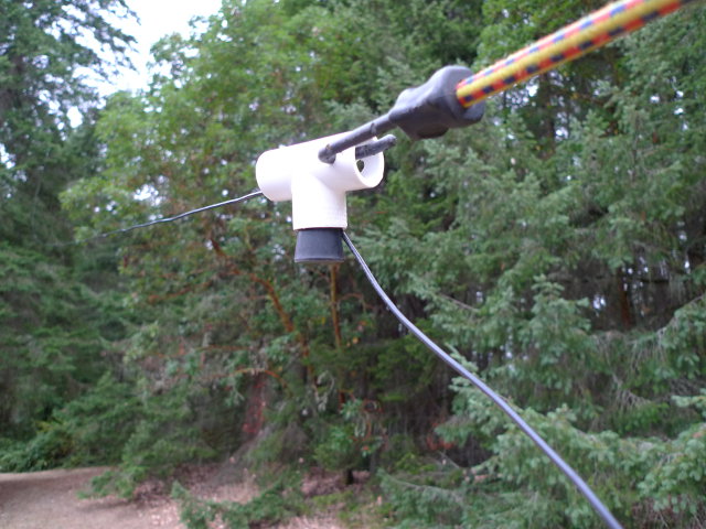
This is what I came up with:
I used shock cord because I hadn’t brought enough rope to the test site.
It’s a 1/2″ PVC tee connector. One of the straight ends has been drilled with a 5/16″ hole for passing an anchoring rope through. The wire passes in through the 90° end and out the end opposite the drilled one. Where it enters, it is secured by a No. 4 rubber stopper; as the tension of the wire pulls on the stopper, it will merely tend to pull the stopper in tighter, thus the stopper holds the wire securely.
A random wire requires a counterpoise, of course: there is in reality no such thing as a “monopole” antenna; all antennas are two-terminal devices. What I am doing is trailing a 60-foot wire along the ground, plus using an alligator-clip lead to ground the tuner to my truck chassis.
How does it work? Quite well, based on my initial results. It seems to get out much better on 75 meters than my previous random wire (which was too short to have a current peak). It’s twice as easy to set up as the doublet (only one end must be launched into a tree, not two). It’s shorter than than the doublet, and installs at an angle, further reducing its real-estate demands. It can fit in a standard campsite. Yet despite the smaller size, unlike the doublet it allows me to operate on 75 meters. I noticed no slippage at the near-end insulator, which behaved exactly as intended.
There is a drawback to this design, and it is RF exposure. Because it doesn’t use transmission line to feed the antenna, this design will radiate in the immediate vicinity of the operator and radio equipment. That’s not so big a deal at QRP power levels, but I wouldn’t want to use this design at higher power. Overall, I consider the freedom to use a simpler antenna design to be yet another advantage of QRP for portable use.
The instructions are unclear on how to connect the rotary encoder. If you look at the encoder from the rear (shaft facing away from you), with two terminals on the left and three on the right, the correct way to wire it is with the black wire on the top terminal and the brown wire on the bottom. The diagram and the written instructions show those two wires reversed, but the photograph in the instructions shows them connected correctly.
This is the correct wiring.
I guessed (incorrectly) that the way in which two pieces of information indicated was the correct way was the way to wire them. I also guessed (correctly) that since the two wires on the other side were for a normally open pushbutton switch, and the middle contact on the encoder side was grounded, the controller was simply detecting which of the brown and black wires were getting grounded in which order to determine the direction of the shaft rotation, so there wouldn’t be any drastic consequences to wiring those two wrong, just reversed tuning.
Naturally I opened it up again, warmed up my soldering iron again, and switched the two wires around. Every normal radio in the known universe has a tuning knob where turning it clockwise makes the frequency go up, and it was very annoying to have a radio that acted in the opposite way.
The official instructions for the uBITX transceiver kit recommend wiring the hot side of the audio out to both the tip and ring connectors. I consider this to be a faulty design and thus an error.
If you plug a stereo device into the jack wired per those instructions, it will work. If you plug a monaural device into the jack, it will cause a short circuit between ring and sleeve, because the sleeve on a mono plug is longer than the sleeve on a stereo one (the tips being the same size, and there being no ring). This short circuit can cause the receiver’s audio section (specifically its output transistor) to self-destruct!
Contrast that with wiring it with the hot side of the audio to tip only, as I recommend. That way you have something that works completely with a monaural device and works somewhat (left channel only) on a stereo device. Works (to at least some degree) with both versus works on one and self-destructs on another. It’s pretty darn obvious which is the better engineering choice.
This is mentioned on uBITX.net, but it isn’t mentioned as prominently as some other errata are (or even labeled as an error), so I figured I’d mention it here. In my opinion, it definitely is incorrect, because it qualifies as faulty design.
It’s particularly nasty because the uBITX receiver is of course a monaural device, making it only logical to assume it has a standard monaural output. Murphy’s Law means that uBITX wired per the standard instructions will sooner or later have an unwitting user (a guest, someone at Field Day, etc.) fall into this pitfall that was laid for them.
What they were trying to do is use a stereo jack in a manner that causes both stereo and monaural devices to fully and properly work. There is a way to do that: use a stereo jack whose sleeve is isolated from ground, and wire ground to ring and hot to tip. This will cause a mono plug to get signal presented at tip and sleeve, and a stereo one to get signal presented at tip and ring. The latter will result in both speakers being connected in series, if the sleeve is isolated from ground.
If the latter is not the case (and it cannot be with a metal case and the stock jacks furnished with the uBITX), ring and sleeve will end up being shorted and you’re back to seeing a signal in the left channel only. Not drastic, but not the full universal performance desired, either.
Instead of using a nonstandard technique that paves the path to a future mishap, it’s far better to just wire it as a mono device and use an easily-obtainable external mono-to-stereo adaptor if you want to feed audio to a stereo device.